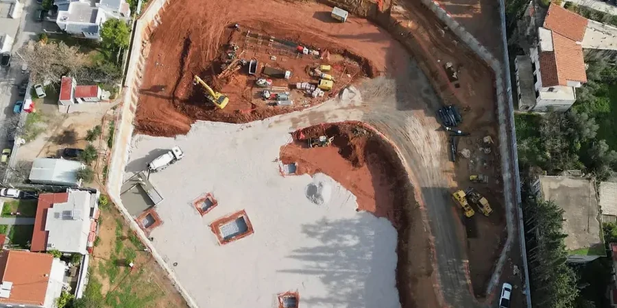
The Oxford Clay under Bedford does not forgive guesswork. We have seen too many projects reach the tender stage with a ground model that treats the entire excavation as a uniform material. It never is. The upper weathered crust behaves differently from the intact stiff clay below. Groundwater perched in the river gravels over the clay adds a second load case that the temporary works must handle. Before setting out the cut geometry, we run a full CPT campaign to map the transition from desiccated crust to competent clay. This single decision changes the earth pressure envelope and often eliminates unnecessary propping levels. The River Great Ouse floodplain introduces further complexity: sand lenses and pockets of organic alluvium appear where the borehole spacing is too wide. A tight grid of in-situ permeability tests in the gravel horizon gives us the seepage rates needed to size the dewatering system. Without that data, the sump pump calculation is just a guess.
In Bedford's Oxford Clay, the difference between a safe 6-metre cut and a bottom heave failure is often just one missing CPT profile through the weathered crust.
Methodology applied in Bedford
Risks and considerations in Bedford
Compare a cut in Brickhill with one in the Castle Road corridor. Brickhill sits on the plateau gravels and the Oxford Clay is deep. The main risk is groundwater drawdown affecting nearby shallow foundations. We specify recharge wells or a secant pile wall to limit the external head drop. Castle Road is different. The river gravels are thin and the clay is closer to surface. Here the dominant failure mode is basal heave. A narrow excavation in stiff clay can fail inwards if the undrained shear strength is overestimated by just 15%. We run a sensitivity analysis on the shear strength profile before fixing the toe level. In both locations, existing brick sewers and Victorian basements add a third dimension. A 2D section through the centre of the cut does not capture the corner effects. We use 3D finite-element models for cuts shorter than 30 metres or where the retained height changes sharply along the perimeter. The extra modelling cost is negligible compared with a single claim for damage to a neighbouring property.
Our services
Our Bedford team delivers the full design chain for deep excavations, from the initial ground investigation specification through to the construction sequence drawings. Each package is checked by a chartered engineer.
Embedded retaining wall design
Sheet pile, secant pile, and diaphragm wall options analysed for the specific ground conditions in Bedford. We produce the bending moment and shear force envelopes, prop levels, and toe penetration required for the permanent and temporary cases.
Construction stage analysis and monitoring specification
Staged PLAXIS or WALLAP models that mirror the contractor's sequence. We define the trigger values for inclinometers, piezometers, and settlement points, referencing the CIRIA C760 alert and alarm thresholds.
Frequently asked questions
How much does a geotechnical design for a deep excavation in Bedford typically cost?
The fee for a complete design package falls between £1,720 and £6,720, depending on the excavation depth, the complexity of the ground model, and the number of construction stages that must be analysed. A simple 4-metre cut with a single prop level sits at the lower end. A 7-metre basement with secant piles, groundwater control, and a 3D corner analysis moves towards the upper end.
Which partial factors does Eurocode 7 require for the Oxford Clay?
We apply the factors from BS EN 1997-1 Annex A. For Design Approach 1 Combination 2, the partial factor on undrained shear strength is 1.40. For Combination 1 it is 1.00. The choice of approach depends on whether the limit state is structural (wall bending) or geotechnical (base heave). We run both combinations and design for the worst case.
Do you need a 3D model for a long straight excavation in Bedford?
Not always. For cuts longer than about twice the retained height, a 2D plane-strain model is normally conservative. We move to 3D when the cut is short relative to its depth, when the retained height changes sharply, or when a corner is within two metres of a sensitive structure. In Bedford's town centre, 3D analysis is common because of the density of adjacent masonry buildings.