Bedford sits at an elevation of roughly 30 metres on the banks of the Great Ouse, and that river has shaped everything about the ground beneath the town. The valley floor is underlain by soft alluvium and river terrace deposits, while the higher ground to the north and east transitions into Oxford Clay and glacial till. Anyone who has excavated a basement on De Parys Avenue or cut into a slope near Brickhill knows the soil profile changes fast. A retaining wall that works perfectly on gravel in Putnoe will not necessarily perform on the compressible silts found closer to the river. Our design approach is built around this local variability: we correlate borehole logs with test pits to map the interface between granular and cohesive strata, and we run triaxial tests on undisturbed samples when the design requires effective stress parameters rather than empirical correlations. The output is a wall section sized for the actual ground, not a generic textbook profile.
A retaining wall in Bedford's river corridor has to work for both drained and undrained conditions, because the water table can rise two metres between August and February.
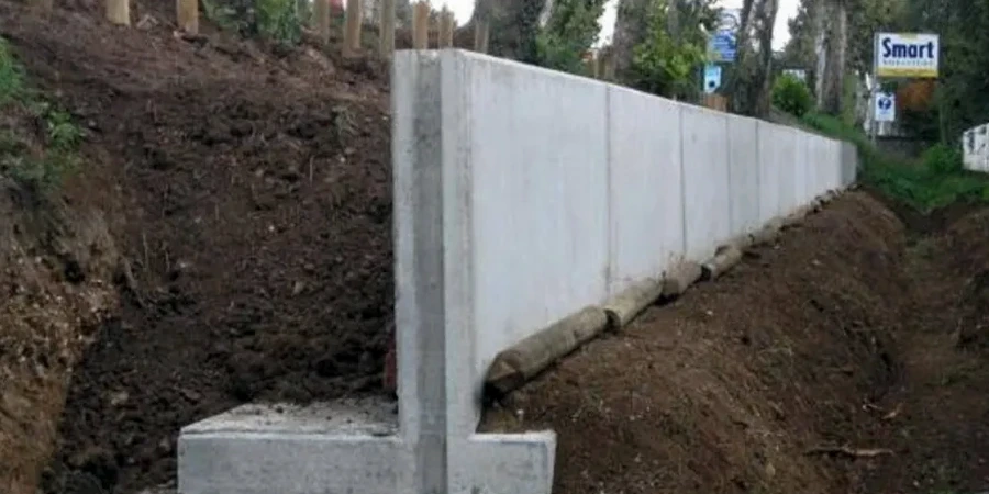
Methodology applied in Bedford
Risks and considerations in Bedford
Compare two sites just three kilometres apart: one on the gravel terrace near Goldington, the other on the floodplain alluvium near Priory Marina. At Goldington, you are founding on dense gravel with an SPT N-value above 30; a gravity wall with a modest base width will satisfy both bearing and sliding checks. At Priory Marina, the top five metres are soft to firm silty clay with undrained shear strength below 40 kPa. A gravity wall there would require a massive concrete section just to resist overturning, and differential settlement could crack the stem. The smarter solution is a lightweight reinforced soil structure or an embedded wall that transfers load below the soft layer. Ignoring this contrast in ground conditions leads to walls that lean, crack, or fail at the construction joint between panels. We have seen the cost of remedial works exceed the original contract value entirely because the ground model was assumed rather than investigated.
Our services
Our retaining wall design service in Bedford covers the full workflow from initial feasibility through to construction support. We work directly for developers, architects, and civil contractors, and we handle the interfaces with building control and warranty providers.
Design and detailing package
Complete structural and geotechnical design of retaining walls including stability checks, reinforcement detailing, drainage specification, and construction sequence drawings. We deliver calculations in a format accepted by NHBC, LABC, and Premier Guarantee.
Ground investigation for retaining structures
Targeted ground investigation to determine the soil parameters required for wall design: boreholes with SPTs, machine-dug trial pits to expose the soil profile, and laboratory testing for strength and compressibility. We specify the investigation scope based on the proposed wall type and site geology.
Construction support and monitoring
Technical support during excavation and wall construction, including review of temporary works proposals, response to ground condition variations, and installation of inclinometers or survey targets where movement monitoring is required by planning conditions.
Frequently asked questions
What retaining wall types are suitable for Bedford's ground conditions?
The choice depends on the soil profile at your specific site. On the gravel terraces, gravity walls and reinforced concrete cantilever walls are often cost-effective because bearing capacity is good. On the floodplain alluvium, we typically recommend embedded walls such as sheet piles or contiguous bored piles, or lightweight reinforced earth structures that reduce bearing pressure. We make the selection based on ground investigation data, not assumptions.
Do I need a retaining wall design for a basement excavation in Bedford?
Yes. Any excavation deeper than 1.2 metres in Bedford requires a formal retaining structure design under CDM 2015 and BS 8002. Basement excavations in the town centre, where adjacent buildings and roads impose surcharge loads, demand a design that limits ground movement. We provide full design packages for basement retaining walls including temporary works if required.
How do you account for the high groundwater levels near the River Great Ouse?
We design the wall for the highest credible groundwater level, typically the winter maximum recorded in local borehole records or Environment Agency data. The design includes hydrostatic and seepage pressures on the retained side, and we specify drainage measures behind the wall to prevent water pressure build-up. If the wall is embedded in low-permeability clay, we also check for long-term pore pressure equalisation.
What is the typical cost for a retaining wall design in Bedford?
For a straightforward retaining wall design in Bedford, fees range from £820 for a small garden wall with clear ground data, up to £3,810 for a full design package covering a basement or commercial retaining structure. The exact cost depends on wall height, complexity of ground conditions, and the level of construction support required.
How long does the design process take from start to finish?
If ground investigation data is already available, we can deliver a concept design within two weeks and a full detailed design within four weeks. If a new ground investigation is needed, the overall programme extends by the time required for drilling, laboratory testing, and factual report preparation. We manage the entire process and can coordinate the ground investigation if you prefer a single point of responsibility.